Author: W.P. Flinn, Updated 12/8/05
For those of you who build your own computers, or wish to do an upgrade of your motherboard and processor, this article is for you. If your motherboard or processor fails, chances are you won't be able to buy an identical replacement, especially if you have had your computer for awhile. Believe it or not, changing your motherboard and processor, while retaining your original hard drive, doesn't necessarily mean that you have to reinstall your entire operating system from scratch.
Description:
Overview: This article describes procedures for replacing an obsolete or defective motherboard and CPU. If a new system is being built from scratch, skip to Step 4 in the procedures.
Before installing any piece of computer equipment, please be sure to read the documentation which comes with the equipment thoroughly. There are a number of issues which will be addressed in this section, including equipment compatibility, safety, installation procedures, and troubleshooting.
Compatibility: It is important to be sure that the form factor of the motherboard being installed is the same as the chassis in which it will be installed. Prior to purchasing a motherboard, measure the inside of the chassis, as well as the positions of any motherboard mounting holes. Note the type and shape of the power supply connector(s) to ensure that they will correctly fit onto the new motherboard. Note the size and location of the keyboard connector hole in the case, to ensure that a motherboard with the proper keyboard and/or mouse type will be used in this case.
It is also important to ensure that the motherboard, CPU and memory are compatible, and will properly connect together, as well as operate correctly once installed. Be sure to consult the system board manufacturer's documentation for compatibility between the motherboard, CPU, and memory.
Safety: Personal and equipment safety are of prime importance when installing equipment inside a computer. Even though the power supply operates at low DC voltages, a shock hazard still exists. Additionally, computer circuit boards are very easily damaged by electrostatic discharge (ESD), and must be handled very carefully.
Tools Needed:
ESD Safe, Grounded Work Mat
ESD Wrist Strap
PC Tool Kit - Phillips Screw Driver, 1/4" Nut Driver
Marking Labels or Tape
Containers for screws and loose hardware
Skill Level:
Advanced
Time Required:
30 - 60 Minutes
Procedures:
Notes:
Proper ESD protection should be used at all times when handling computer circuit boards.
Computer power should be off and the cord disconnected prior to performing any procedures with the computer case opened.
Leave all circuit cards in their proper containers until ready for use.
Motherboard and CPU Replacement:
-
If computer is still operational, backup ALL critical data on computer before proceeding with the replacement of the motherboard and CPU hardware. If the computer was not operational, you can boot the computer AFTER new motherboard and CPU are replaced, but BEFORE the first boot to the old hard drive using a Knoppix CD, mount the hard drive volume, and attempt to recover the data before proceeding.
Note: Instructions for recovering data with Knoppix found Here
-
Remove the computer's chassis cover, and locate all of the motherboard's essential hardware and electrical connections. Figures 1 - 3 below are an example of a typical ATX form factor tower case assembly:
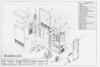
Figure 1
Computer Case and Components
Click on image for full-size view
Figure 2
Computer Case and Components
Click on image for full-size view
Figure 3
Computer Case and Components
Click on image for full-size view
-
Remove the adapter cards and old motherboard, and put all hardware in a safe place, preferably an ESD safe work mat. All loose hardware, such as fasteners and jumpers, should be placed in a sealable container.
-
Disconnect all power connectors and front panel connectors from the motherboard. Be sure to document all power and front panel connections for easy reassembly. If the connectors are not labeled, use labeling tape to mark each connector. Be sure to consult the motherboard documentation for familiarity with the location and polarity of the connectors on the new motherboard.
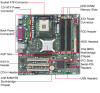
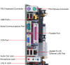
Figure 4
Motherboard and Rear Panel Connectors
Click on images for full-size view
-
Perform a thorough inspection of the chassis to look for loose or broken fasteners, cabling, or other components. Clean the inside of the case to remove all dust from the chassis, power supply, and any other components inside the computer.
-
Carefully open the container for the new motherboard, and inspect the new motherboard to ensure that all required parts are attached, and to look for broken or damaged components.
-
Configure all jumpers and switches, in accordance with the motherboard documentation, for compatibility with the CPU and memory being installed.
-
Locate and measure the position of all of the motherboard mounting holes in the bottom of the chassis motherboard mounting plate. Be sure to note which holes are used for plastic standoffs, and which holes are used for copper grounding screws (See Figure 1, Number 15). Insert the copper or brass grounding screws into the appropriate position(s) in the chassis. Insert the plastic motherboard standoffs into the chassis.
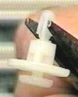
Figure 5
Plastic Standoff
-
Carefully mount the motherboard onto the mounting hardware that was just placed on the chassis. Be sure to line up the necessary motherboard mounting holes with the brass mounting nuts.
-
Locate the motherboard mounting screws, and the insulating washers, and insert them into the appropriate places in the motherboard holes with brass mounting nuts.
-
Insert the CPU into its socket/slot, and attach any cooling devices (i.e. fans/heat sinks) which are required. Insert the RAM modules at this time also.
-
If the motherboard is being mounted into a tower case, with a removable bottom chassis plate or drawer (See Figure 1, Number 6), position the mounting plate and motherboard into the main chassis, and loosely tighten the mounting screws.
Note: Do not tighten the plate or drawer mounting screws all the way into the chassis until the adapter cards are in place, as this may cause improper adapter card alignment.
-
Replace any adapter cards into their slots, being sure to check for proper alignment with the back of the computer chassis, as well as seating into the slots.
-
Connect the power supply connectors into the appropriate connectors on the motherboard, CD-ROM, hard drive and floppy drive.


Restoring the Operating System (If not installing OS from scratch):
Note: This step is necessary only if the original hard drive is to be replaced in the computer, and you don't want to reinstall the OS from scratch. This procedure will cause the existing Windows XP installation to detect the new motherboard and CPU hardware.
-
Before proceeding, ensure you backed up all data as mentioned in the procedure above. If the computer was not operational before the hardware change, you can boot the new motherboard and CPU to a Knoppix CD, mount the hard drive volume, and attempt to recover the data before proceeding. Do this BEFORE the first boot to the old hard drive.
Note: Instructions for recovering data with Knoppix found Here
-
Place the Windows XP CD into the CD-ROM drive and boot to the CD.
-
Follow the prompts as if installing the OS from scratch until the screen in Figure 6 is reached
Figure 6
Welcome to Setup
-
When the screen above appears, press ENTER to setup Windows XP. Do NOT select "R" to repair the installation at this time.
-
Proceed until the screen in figure 7 appears.
Figure 7
Repair/Install Screen
-
When the screen in Figure 7 above appears, ensure that the partition with the Windows XP installation is highlighted and then press "R" to repair the Windows installation that already resides on the hard drive.
-
Allow the installation to continue and reinstall all necessary drivers for the installed hardware.
Troubleshooting:
System Won't Power-up:
-
Check to make sure unit is plugged in to power cord and to wall outlet.
-
Check all power supply connections.
-
Check for proper polarity and connector orientation of AT type power supplies.
-
If replacing with a Pentium 4 motherboard, ensure the old power supply is Pentium 4 ready and has an additional 4 pin 12 volt power connector required for the motherboard to power the CPU. If not, purchase a new Pentium 4 ready power supply..
Hard Drive and/or Power Lights Won't Light:
-
Check for polarity and orientation of HDD and/or power light connectors on motherboard front panel connectors. The lights are light emitting diodes (LEDs) and their connections are polarity sensitive.
System Will Not Boot Up:
-
Check for orientation and connection of all IDE cables on IDE controller.
-
Ensure all hard drives are connected to proper cable.
-
Check BIOS/CMOS settings to be sure hard drive is detected and configured properly.
-
Be sure a bootable diskette is inserted into the floppy drive if hard drive will not boot.
-
Be sure hard drive and/or floppy drives are formatted with system files.
Video Faulty, No Display, or Several Beeps on POST:
-
Check for proper alignment and seating of video card.
-
Remove video card, and reseat back into its slot, carefully tighten mounting plate into chassis.
-
If new motherboard has an internal video card, remove additional video cards and plug monitor into motherboard video card.
System Won't Boot, Hard Drive Not Recognized:
-
Enter SETUP and check for proper hard drive configuration.
-
Check hard drive cables to ensure proper data cable connection.
-
Check hard drive power cable.
World Wide Web Resources: